The
need for a dimensional tool |
Data
input requirements for CPPA Overview of
the CPPA process |
|
|
| Projection of
Computer 3d reconstruction model A post fire photograph of the Nautilus room showing the floor burn patterns is digitized into a computer image file using a flatbed scanner. The computer image file is then loaded into 3d StudioMAX (3D modeling and animation software) as a background image. |
 |
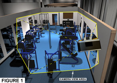
3d Studio MAX has the
ability to generate a virtual camera that can simulate
that of a real world camera. This camera can be placed
anywhere within the computer generated environment of the
fitness center. Figure 1 illustrates the virtual camera
looking South into the Nautilus room.
|
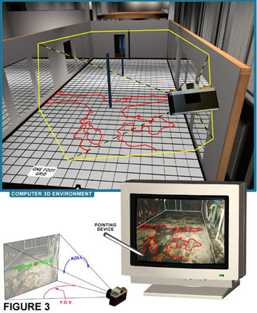
A view port on the computer monitor represents what the virtual camera sees and is similar to looking through a camera viewfinder. This view port displays the post fire photograph as a background image. As shown in Figure 2, a wire-frame representation of the 3D model geometry is concurrently projected onto the background image. The wire-frame represents key elements in the Nautilus room, such as the floor perimeter, walls, and structural steel. |
| The first step in
establishing a computer photo perspective match is the
alignment of the wire-frame to the post-fire photograph.
Key elements identified as the same in both the
wire-frame and the post-fire photograph are used as
guides for alignment. |
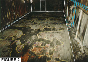
| Alignment
Process The alignment process begins by placing the virtual camera and its target (center of view) at the approximate location of their real world counterpart. It should be noted that AutoCad and 3d Studio MAX are dimensionally accurate and they relate to real world dimension units such as feet, inches, meters, and centimeters. The alignment process continues by refining the camera placement and other camera parameters including lens focal length (field of view) and roll (tilt), until there is a direct visible correlation between similar key elements in the background image and in the projected wire-frame. Mapping
Process |
|
|
|
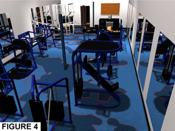
The end result is a series of two-dimensional shapes representing the floor burn patterns which is integral with the existing 3d construction model. Figure 4 shows the floor burn patterns in relationship to the contents in the Nautilus room. If three-dimensional data is required of the object or area of interest in the background image, then the second step in this process is repeated with the theoretical two-dimensional plane defined on an alternate axis. |
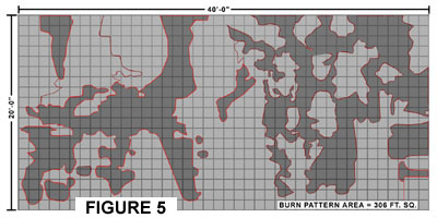
| Area
Calculation The 2d shapes representing the floor burn patterns are considered to be valid geometry by both AutoCAD and 3d Studio MAX (r2). After a simple query is made, either program calculates the area. Figure 5 presents a plan view of the floor burn patterns and the burn pattern area in the Nautilus room. |
 |
Tel: 510-527-7300 u gus@originpointinc.com u 7023 Stockton Avenue, El Cerrito, CA 94530 |