The following is an excerpt from a report entitled "Three Dimensional Computer Animation of the Pearblossom Pumping Plant", and describes the generation of a Digital Terrain Model (DTM).
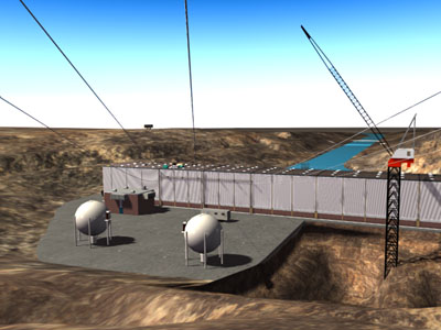
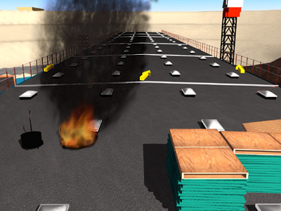
The terrain within the study area was modeled using a computer aided drafting application called AutoCad and digital terrain modeling applications called COGO/DTM. COMPUTER 3D RECONSTRUCTION MODEL OF THE PPP This section describes the techniques used to generate a 3D mesh representation of the site and is referred to as a Digital Terrain Model (DTM). The projection of roads onto the DTM and the 3D reconstruction of the PPP structure are discussed. A site survey that was conducted in order to verify the accuracy of the virtual PPP environment is also discussed. This section ends with the modeling and placement of roofing equipment and supplies on the PPP roof. The computer 3d reconstruction of the PPP and it’s environs makes up a study area that is 3462 feet wide (east-west) by 4734 feet high (north-south). The coordinates defining the study area boundary are based on the NAD 27 CAL State Plane Coordinate Grid System, Zone 7, and are as follows:
Generation of the Digital Terrain Model Topographic maps which are drawn to scale were used as the foundation data to recreate the terrain in 3D on the computer. These maps include elevation contours, "spot" elevations, road outlines, and survey control (e.g., CL ,, traverse line, coordinate grid). Elevation contours from the maps entitled "Topographic Map of "Antelope Valley Drainage Study"" were used to generate the virtual 3D terrain of the study area around the PPP. Contours are lines drawn on a plan that connect points having similar elevations and represent an even value. It is commonly accepted that elevations can be determined to half the contour interval. The aforementioned maps have five foot contour intervals, thus elevations to the closest two and one half feet are determined. Map Digitization Map digitization is accomplished by scanning the maps using a color flatbed scanner. The computer image is composed of a finite amount of pixels and is known as a raster image. The amount of pixels and the quality of the image are determined by the resolution at which the map was scanned or digitized. The color flatbed scanner used is capable of a maximum resolution of 160,000 pixels per square inch. This resolution level limits the possibility of introducing aspect and distortion error and is more than adequate in maintaining the integrity of the source material. Each raster image is then loaded into AutoCad. The following maps were digitized into computer image files:
Raster to Vector Conversion The raster image is displayed in AutoCad as a background image in a view port on the computer monitor. Pertinent information such as the elevation contours are turned into vectors by means of tracing over the contour lines within the view port. The purpose of tracing the raster image in AutoCad is to convert the contour lines, roads, and survey points into vectors, or more simply, into a series of directions and distances that the computer can understand. These vectors are known as polylines in AutoCad. Since this is a vector driven application, the resultant polylines representing the contour lines are interpreted by AutoCad as valid geometry. Establishment of the CAL State Plane Coordinate Grid System The next step is to establish the original drawing scale in terms of real world coordinates. The initial scale of the image after digitization is equivalent to the original size of the plan or map itself. (If the original map was 11" x 17", then the digitized image would be acknowledged as 11" x 17" in the AutoCad drafting environment). Since the original maps and plans were drawn to scale, the next step is to identify reference (control) points from the resultant vectors that pertain to true scale. This information is derived from the coordinate grid and annotated survey control markers. The vectors representing contours and other pertinent information are then scaled to adapt real world coordinates within the virtual computer environment. At this point a series of polylines in AutoCad represent the original elevation contours from the map at the correct real world scale (1:1) in two dimensions. These two dimensions are recognized as horizontal, rectangular coordinates that define two perpendicular axes. These two axes are referred to as Northing (north-south) and Easting (east-west). The horizontal coordinate values found in all the maps pertaining to the PPP adhere to either Zone 5 or 7 of the NAD 27 CAL State Plane Coordinate Grid System. Elevation data is derived from numeric labels found on every fifth contour line on the original maps. These labels define the third dimension by establishing the vertical elevation of the contour line in feet above mean sea level (MSL). The vertical coordinate values found in all maps pertaining to the PPP adhere to the North American Vertical Datum 1929 (NAVD 29). The existing 2D polylines representing the contour lines are moved to the appropriate elevation within AutoCad. This completes the necessary translation of the source information into the computer environment, and will be referred to as Digital Survey Data (DSD).
Digital Terrain Model Computer applications called COGO/DTM are loaded into the AutoCad environment and are responsible for the interpretation of the digital survey data into a graphical 3D mesh representation of the study area around the PPP. COGO/DTM interpolate the DSD into a Triangular Irregular Network (TIN). These applications derive points with elevations from the contour polylines in the DSD, and then connect the points by lines into triangles. The "3D Faces" command is executed from within COGO/DTM and a 3D surface model of the TIN is created at a user specified grid spacing. In this case, a 10’ x 10’ grid spacing for the terrain in the immediate area of the PPP and a 50’ x 50’ grid spacing for the remainder of the study area are used. This surface model of the terrain is made up of a series of triangular faces. Each face contains three points connected by lines which make up the boundary of a planar surface. The end result is much like a wire-frame with a canvas skin stretched over it. The resulting 3D Digital Terrain Model is loaded into 3D Studio. Road Projection onto 3D Digital Terrain Model The translation of the roads from a digitized raster image into vectors is conducted in the same manner as noted earlier in this report. Since all the maps and plans adhere to the NAD 27 CAL State Plane Coordinate Grid System, alignment of all information is automatic. Three different maps were used, and redundant road information is superseded by most recent map date. In the AutoCad drafting environment, the road outlines are converted into closed polygons. These closed polygons are made up of a series of coplanar 3D faces, and do not retain elevation data. The road outlines represented as closed polygons are loaded into 3D Studio. In 3D Studio, the closed polygons are rendered and converted back into a single raster image. This raster image is then projected onto the surface of the DTM. This is analogous to a slide projector projecting onto a lumpy screen. |
Tel: 510-527-7300 u gus@originpointinc.com u 7023 Stockton Avenue, El Cerrito, CA 94530 |